
Developer Kits
PMD Developer Kits
Overview
Every PMD developer kit ships with Pro-Motion®, a Windows-based motor configuration/tuning software, an SDK (software development kit), a range of software design examples, and reference circuit board (schematic) designs.
Full Developer Kit List (9 kits)
| Kit | Target Product | Description |
|---|---|---|
| ION/CME N-Series Developer Kit | ION/CME N-Series drive | Hardware/software package for developing motion applications based on the N-Series drive |
| DK58113 | Magellan MC58113 IC | Development board and software for the single-axis position control IC |
| DK58420 | Magellan MC58000 / MC55000 IC | Development board and software for multi-axis position control / pulse & direction generation ICs |
| DK78113 | Juno MC78113 IC (64-pin TQFP) | Development board and software for the velocity control IC |
| DK73112N | Juno MC73112N IC (56-pin VQFN) | Development board and software for the torque control IC |
| DK74113N | Juno MC74113 IC (56-pin VQFN) | Development board and software for the step motor control IC |
| Atlas Amplifier Developer Kit | Atlas digital amplifier | Board connecting a Magellan IC developer kit (DK58113/DK58420, etc.) to Atlas amplifiers, 1–4 axis configurations |
| Prodigy/CME Developer Kit | Prodigy/CME machine controller board | Hardware/software package for the machine controller board |
| ION 500 & 3000 Developer Kit | ION 500 / ION 3000 drive | Drive development package including PC, motor, and peripheral connection cables |
Common Contents
- Pro-Motion® (Windows-based motor setup/tuning software) — cuts system setup time from days to hours
- SDK (software development kit)
- Software design examples
- Full set of verified reference circuit board (schematic) documentation
N-Series ION Developer Kit Assembly — Original Diagrams
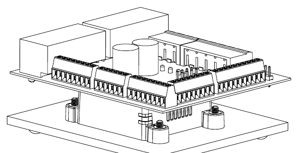
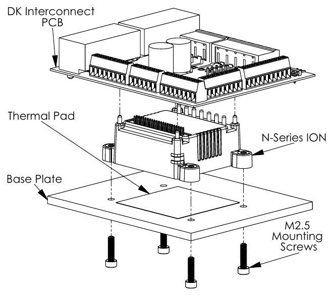
These are the original assembly diagrams from the jointly published Portescap/PMD Portescap Motor Application Development Kit User Manual. They show the DK interconnect PCB, thermal pad, N-Series ION drive, base plate, and four M2.5 mounting screws assembled into a single stack.
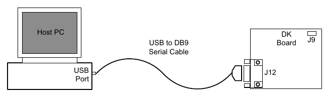
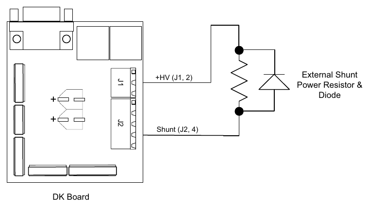
DK Interconnect Board & Wiring
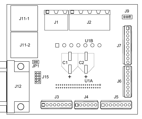
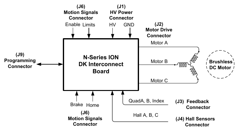
See the original manual diagrams for which signal each board connector (J1–J15) carries, and how they're actually wired to Portescap brushless DC motors.
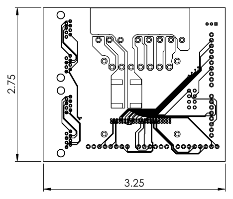
Physical Dimensions
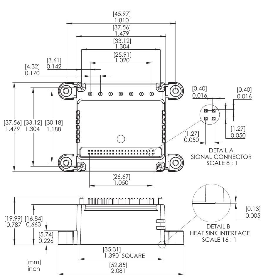
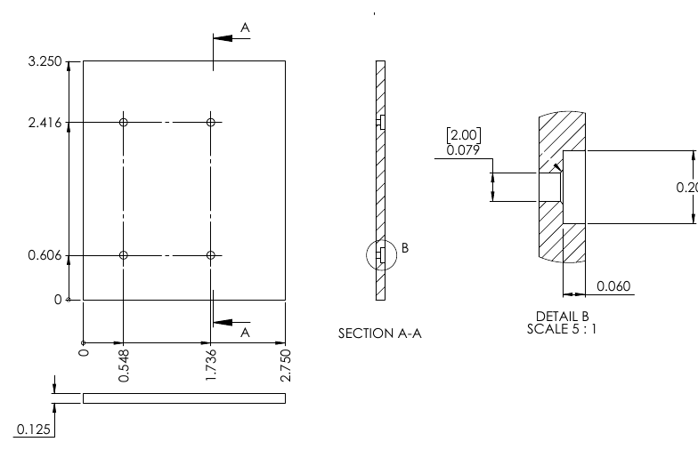
Actual dimension drawings of the N-Series ION drive, DK base plate, and interconnect board are provided for mechanical design reference (units: mm [in brackets] / inch).
Schematics (Detailed Engineering Reference)
The complete original schematic of the Serial Host Interface DK interconnect board, for custom board design or in-depth troubleshooting.

All diagrams above are excerpted from the jointly published Portescap/PMD Portescap Motor Application Development Kit User Manual (Rev 0.96).